
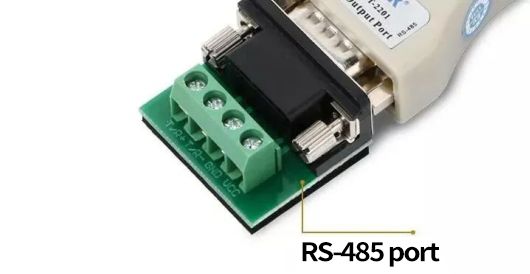
What is the concept of the RS485 interface first?
In short, it is a standard for electrical characteristics, which is defined by the Telecommunications Industry Association and the Electronic Industries Alliance. The digital communication network using this standard can effectively transmit signals over long distances and in environments with high electronic noise. RS-485 makes it possible to configure low-cost local networks and multi branch communication links.
RS485 has two types of wiring: two wire system and four wire system. The four wire system can only achieve point-to-point communication and is rarely used now. Currently, the two wire system wiring method is mostly used.
In weak current engineering, RS485 communication generally adopts a master-slave communication method, that is, one host with multiple slaves.
If you have a deep understanding of RS485, you will find that there is indeed a lot of knowledge inside. Therefore, we will choose some issues that we usually consider in weak electricity for everyone to learn and understand.
RS-485 Electrical Regulations
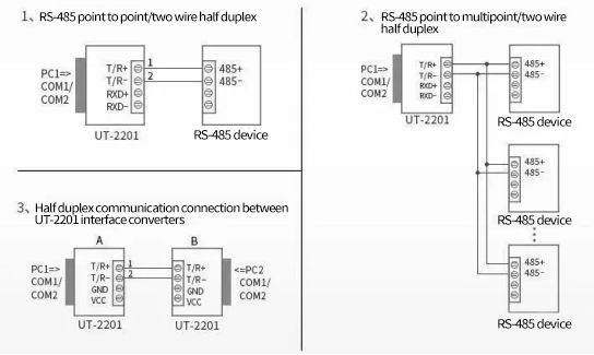
Due to the development of RS-485 from RS-422, many electrical regulations of RS-485 are similar to RS-422. If balanced transmission is adopted, termination resistors need to be connected to the transmission line. RS-485 can adopt two wire and four wire methods, and the two wire system can achieve true multi-point bidirectional communication, as shown in Figure 6.
When using a four wire connection, like RS-422, it can only achieve point-to-point communication, that is, there can only be one master device and the rest are slave devices. However, it has improvements compared to RS-422, and can connect 32 more devices on the bus regardless of the four wire or two wire connection method.
The RS-485 common mode voltage output is between -7V and+12V, and the minimum input impedance of the RS-485 receiver is 12k;, The RS-485 driver can be applied in RS-422 networks. RS-485, like RS-422, has a maximum transmission distance of approximately 1219 meters and a maximum transmission rate of 10Mb/s. The length of the balanced twisted pair is inversely proportional to the transmission rate, and the specified maximum cable length can only be used when the speed is below 100kb/s. The highest rate of transmission can only be achieved over a very short distance. Generally, the maximum transmission rate of a 100 meter long twisted pair is only 1Mb/s. RS-485 requires two terminating resistors with a resistance value equal to the characteristic impedance of the transmission cable. When transmitting at a rectangular distance, there is no need for a terminating resistor, which is generally not required below 300 meters. The terminating resistor is connected at both ends of the transmission bus.
Key points for network installation of RS-422 and RS-485
RS-422 can support 10 nodes, while RS-485 supports 32 nodes, so multiple nodes form a network. The network topology generally adopts a terminal matched bus structure and does not support ring or star networks. When building a network, the following points should be noted:
1. Use a twisted pair cable as the bus and connect each node in series. The length of the outgoing line from the bus to each node should be as short as possible to minimize the impact of the reflected signal in the outgoing line on the bus signal.
2. Attention shall be paid to the continuity of bus characteristic impedance, and signal reflection will occur at the Classification of discontinuities of impedance. The following situations can easily lead to this discontinuity: different sections of the bus use different cables, or there are too many transceivers installed closely together on a certain section of the bus, or too long branch lines are led out to the bus.
In short, a single, continuous signal channel should be provided as the bus.
How to consider the length of the transmission cable when using the RS485 interface?
Answer: When using the RS485 interface, the maximum cable length allowed for data signal transmission from the generator to the load on a specific transmission line is a function of the data signal rate, which is mainly limited by signal distortion and noise. The relationship curve between the maximum cable length and signal rate shown in the following figure is obtained using a 24AWG copper core twisted pair telephone cable (with a wire diameter of 0.51mm), with a line to line bypass capacitance of 52.5PF/M, and a terminal load resistance of 100 ohms.
When the data signal rate decreases to below 90Kbit/S, assuming a maximum allowable signal loss of 6dBV, the cable length is limited to 1200M. In fact, the curve in the figure is very conservative, and in practical use, it is possible to achieve a cable length larger than it.
When using cables with different wire diameters. The maximum cable length obtained is different. For example, when the data signal rate is 600Kbit/S and a 24AWG cable is used, it can be seen from the figure that the maximum cable length is 200m. If a 19AWG cable (with a wire diameter of 0.91mm) is used, the cable length can be greater than 200m; If a 28AWG cable (with a wire diameter of 0.32mm) is used, the cable length can only be less than 200m.
How to achieve multi-point communication of RS-485?
Answer: Only one transmitter can send on the RS-485 bus at any time. Half duplex mode, with only one master slave. Full duplex mode, the master station can always send, and the slave station can only have one send. (Controlled by and DE)
Under what conditions does terminal matching need to be used for RS-485 interface communication? How to determine the resistance value? How to configure terminal matching resistors?
Answer: In long-distance signal transmission, it is generally necessary to connect a terminal matching resistor at the receiving end to avoid signal reflection and echo. The terminal matching resistance value depends on the impedance characteristics of the cable and is independent of the length of the cable.
RS-485 generally uses twisted pair (shielded or unshielded) connections, with a terminal resistance typically between 100 and 140 Ω, with a typical value of 120 Ω. In actual configuration, one terminal resistor is connected to each of the two terminal nodes of the cable, the closest and farthest, while the node in the middle cannot be connected to the terminal resistor, otherwise communication errors will occur.
Why does the RS-485 interface still have data output from the receiver when communication is stopped?
Answer: Since RS-485 requires all transmission enable control signals to be turned off and reception enable to be valid after sending data, the bus driver enters a high resistance state and the receiver can monitor whether there is new communication data on the bus.
At this time, the bus is in a passive drive state (if the bus has a terminal matching resistance, the differential level of lines A and B is 0, the receiver's output is uncertain, and it is sensitive to the change of differential signal on line AB; if there is no terminal matching, the bus is in a High impedance state, and the receiver's output is uncertain), so it is vulnerable to external noise interference. When the noise voltage exceeds the input signal threshold (typical value ± 200mV), the receiver will output data, causing the corresponding UART to receive invalid data, causing subsequent normal communication errors; Another situation may occur at the moment when the transmission enable control is turned on/off, causing the receiver to output a signal, which can also cause UART to receive incorrectly. Solution:
1) On the communication bus, the method of pulling up (A line) at the same phase input end and pulling down (B line) at the opposite phase input end is used to clamp the bus, ensuring that the receiver output is at a fixed "1" level; 2) Replace the interface circuit with MAX308x series interface products with built-in fault prevention mode; 3) Eliminating through software means, that is, adding 2-5 initial synchronization bytes within the communication data packet, only after the synchronization header is met can real data communication begin.
Signal attenuation of RS-485 in communication cables
The second factor that affects signal transmission is the attenuation of the signal during cable transmission. A transmission cable can be seen as an equivalent circuit composed of a combination of distributed capacitance, distributed inductance, and resistance.
The distributed capacitance C of a cable is mainly generated by two parallel wires of a twisted pair. The resistance of the wire has little effect on the signal here and can be ignored.
The Influence of Distributed Capacitance on the Transmission Performance of RS-485 Bus
The distributed capacitance of a cable is mainly generated by two parallel wires of a twisted pair. In addition, there is also a distributed capacitance between the wire and the ground, which, although very small, cannot be ignored in the analysis. The impact of distributed capacitance on bus transmission performance is mainly due to the transmission of fundamental signals on the bus, which can only be expressed in "1" and "0" ways. In a special byte, such as 0x01, the signal "0" allows sufficient charging time for the distributed capacitor. However, when the signal "1" arrives, due to the charge in the distributed capacitor, there is no time to discharge, and (Vin+) - (Vin -) - is still greater than 200mV. This results in the receiver mistakenly believing it to be "0", ultimately leading to CRC verification errors and the entire data frame transmission error.
Due to the influence of distribution on the bus, data transmission errors occur, resulting in a decrease in the overall network performance. There are two ways to solve this problem:
(1) Reduce the Baud of data transmission;
(2) Use cables with small distributed capacitors to improve the quality of transmission lines.
Follow CF FIBERLINK to learn more about security expertise!!!
Statement: Sharing high-quality content with everyone is important. Some articles are sourced from the internet. If there are any infringements, please let us know and we will handle them as soon as possible.
Post time: Jul-06-2023